DESIGN GUIDES
|
Best Practice Best practice design guides aim to help create complex shapes while:
• Allowing plastic to flow easily and uniformly around the part. • Allowing plastic to flow easily and uniformly around the part. • Allowing the plastic to cool quickly and evenly, resulting in a stable and accurate part.
These general tips will improve part quality, mould ability and cycle time based on known implementation and characteristics of the injection moulding process.
Note: Design guides are broken often and still result in successful moulded parts.
To do achieve this careful consideration and understanding of many parameters is needed including;
• The part’s mechanical requirements, • Mould flow, • Temperature control within the tool, • Polymer selection • Filler requirements • Adjustment of part geometry.
|
.. |
|
|
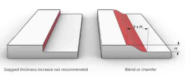
Uniform Wall thickness
Keep walls constant thickness, and avoid thick sections If different thickness are required ensure the transition is smooth by blending or chamfering.
Transition over 3 x thickness difference.
Background Even wall sections allow the material to flow at a constant rate around the tool. Variable walls can lead to the part warping as the material cools. See table for recommended wall thickness
|
|
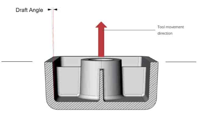
Draft
Allow as much draft as possible.
Recommended draft is >2 °
Increase draft 1° per 25mm height on tall features.
If the part is to be textured add 1-2°.
Background At the end of the moulding cycle, the cooling part needs to be ejected from the tool. Without draft, as the part shrinks it grips the vertical walls requiring greater force to push it off. This can result in a number of defects including ejector punch marks or drag marks where material rubs against the tool.
For this reason taper is applied at an angle to the movement direction of the tool. With sufficient draft on all surfaces the part quality will improve and the cycle time will reduce.
Draft also helps with the CNC milling process to create the mould tools, allowing deeper features.
|
|
|
|
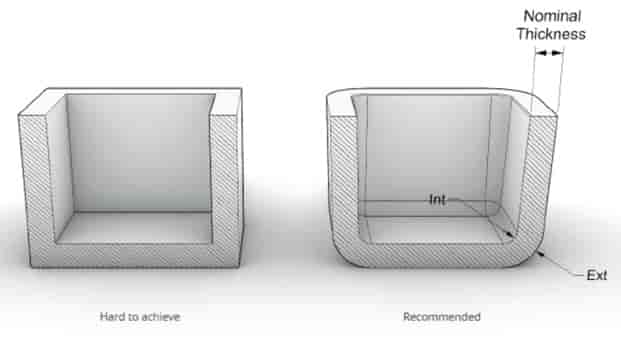
Round Edges
For interior edges apply a radius >0.5x Wall thickness.
Exterior edges should have a radius of Interior radius + Wall thickness.
Background As with wall sections, ensuring that the plastic can flow easily round the part is essential to avoid warping.
Sharp corners restrict the flow as they temporarily widen the flow path, and change direction quickly. This results in inherent stress within the part.
|
|
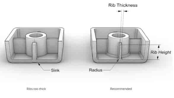
Use Ribs for Strength
Rib thickness should be 40 – 60 % of the primary wall thickness. The height of a rib should be < 3x the thickness of the primary wall. Ribs should be drafted >0.5 °. There should be a radius of ¼ the primary wall thickness. Ribs should be at least 2 x nominal thickness or ideally their height apart.
Background The requirement for keeping wall sections thin require consideration to introduce strength into a part. Ribs can be used to achieve strength and volume where needed.
It is important to consider the plastic flow and resultant material thickness when placing a rib. If the area at the base of the rib becomes too thick the plastic will cool slower and cause a visible sink mark.
Shorter ribs minimise ejection problems and also make it easier to fill the part. Multiple ribs should be place no closer than their height from each other.
|
|
|
|
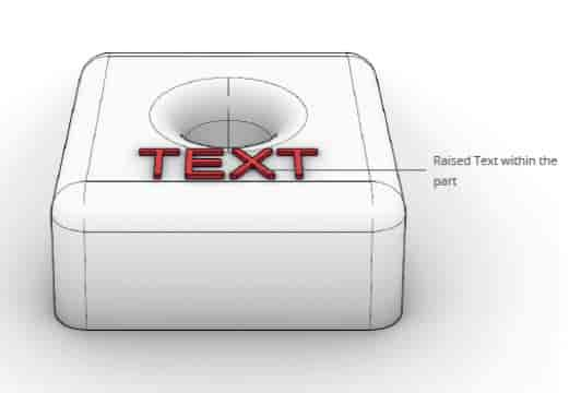
Text
Recommendation Use a bold San Serif font minimum 20 point. (5mm height).
Use raised (Embossed) text rather than engraved.
Raise the text by 0.3 – 0.5mm.
Ensure the text is perpendicular to line of draw.
Background The Tools will be created by CNC so for cost finish and accuracy it is preferred to de-boss the lettering into the tool which results in an embossed plastic part.
|
|
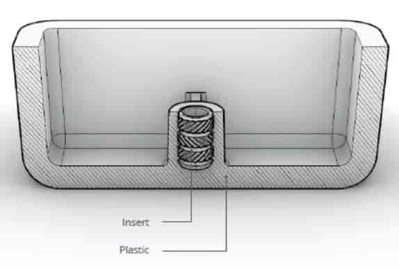
Screw Bosses
Boss diameter = 2.0 to 2.4 x Hole (Screw/insert) diameter Bottom fillet = 1/4 Nominal wall section Rib height= 1/2 Wall height
Background As with ribs, screw bosses require careful design to avoid thick sections at the base.
Ribs and supporting gussets are often necessary to give sufficient strength, whilst keeping the volume of material down.
Avoid merging bosses with side walls, as the sections become thick leading to sink marks.
If the position is needed in some cases features can be created as shown to even the wall sections.
|
|
|
|
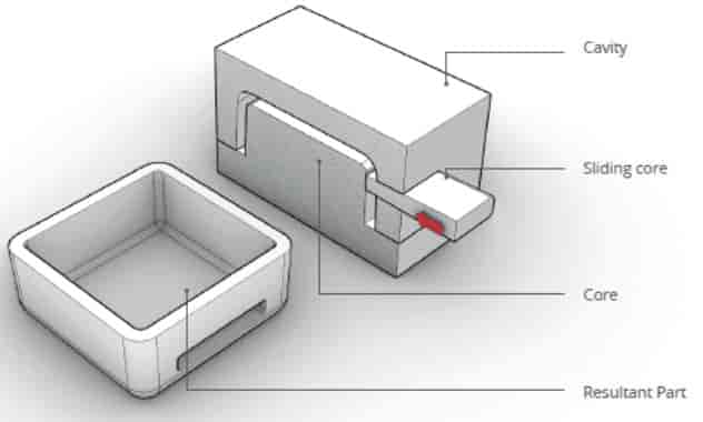
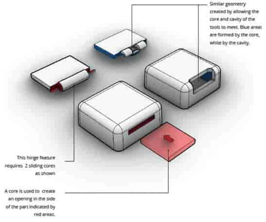
Undercuts - Sliding Cores There is often the need to create features which require an under cut, such as snap fits or holes perpendicular to tool movement. A common way to make undercuts is to use sliding cores.
Sliding cores are moving tool parts which move through or between the main tools temporarily creating a volume for the plastic to flow around, and then removed as the tools open.
The sliding cores need to be drafted in line of movement: 1 degree or more will be needed where the core meets plastic.
3-5 degrees is recommended where two parts of the tool slide together.
The use of sliding cores need to be carefully considered. Each one will add cost, and will introduce a part line with potential for flashing.
Discussion will be needed with the tool maker to ensure enough space is available for the core to slide, and enough material in the tool around the sliding core for reliability.
|
|
Shut offs
Avoiding an undercut all together is often the best option. This can sometimes be done by changing the way the two parts of the mould meet.
Shut-offs offer low tooling cost approaches to creating features which would otherwise be achieved by sliding cores.
A shut off is where two parts of the mould mate, preventing plastic from passing. It is used to describe where the moulds form a slot or a hole by this method, or when a slide shuts against the core or cavity.
As well as the plastic guidelines the tool geometry needs to be considered. As the 2 parts move against each other, they will wear, shortening the tool life. Tool strength is also a consideration, and often features need to be adapted to keep enough tool material.
For this reason 3-5 ° draft is required between the mating tools.
|
|
|
|
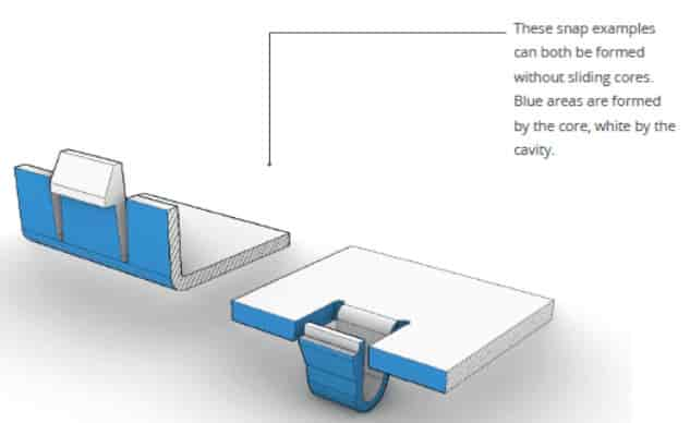
Snap Fits
Snap fits are often used to hold plastic parts together because they are quicker and lower cost to implement than screws.
Snaps inherently require a overhanging feature which is often undercut, however to keep costs low it is often possible to create snaps in line of draw using the partline and shut-off.
There are many ways to create a snap fit. The snap design will depend on a number of variables specific to your project including space available:
• Material choice • Snap force • Retention force • Opening requirement |