BASIC PRINCIPLES
Injection moulding is a formative manufacturing technology, i.e. material is formed from an amorphous shape into a fixed shape defined by a mould tool. Almost every plastic part created today is by injection moulding as it allows identical parts to be created in huge numbers, in a short space of time, and at very low cost per part.
The process works as follows:
1. A mould cavity defines the shape of the part.
2. Material (melted plastic) is injected under pressure into the cavity.
3. When the plastic cools it solidifies to take the form defined by the mould.
4. The part is ejected, and the process repeats from step 2.
Part Creation
Whilst the part cost is low, injection moulding has high set up costs, mostly from the cost to make the tools (using CNC) Mould tools range from a few hundred GBP to over 100,000 GBP depending on complexity.
The materials used for the tools varies depending on how many parts are to be made and the accuracy required. All thermoplastics (polymer’s which becomes soft when heated and harden when cooled) can be moulded. Some silicones and thermoset resins are also possible to mould.
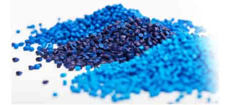
The most common thermoplastics used are:
• Polypropylene (PP)
• Acrylonitrile butadiene styrene (ABS)
• Polyethylene (PE)
• Polystyrene (PS)
ADVANTAGES AND DISADVANTAGES OF INJECTION MOULDING
Advantages
• Suitable for very high volumes >500 pieces
• Extremely quick to make parts (once running)
• A large range of materials available with diverse properties
• Very low part cost in large volumes.
• Excellent repeatability
• High tolerance
• Excellent visual appearance
• Can create very complex geometry
• Little or no extra finish required
• Low scrap rates
Disadvantages
• High set up costs for tooling
• Long lead time relative to other processes.
• Expensive to modify design
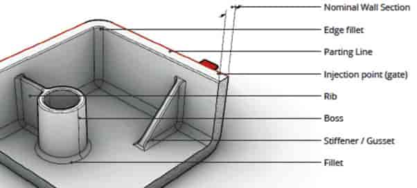
MOULDING PRINCIPLES
|
Parts Anatomy Shown here are a number of the terms that will be covered through-out this manufacturing guide. Nominal Wall Section: The general thickness of the main part walls Parting line: Where parts of the tool meet Injection point: Where plastic enters the mould cavity Rib: Used to give a part stiffness Fillet: Rounds a corner to help plastic flow
Gusset: Stiffens a part, usually across 90 degrees between vertical and horizontal |
 |
|
|
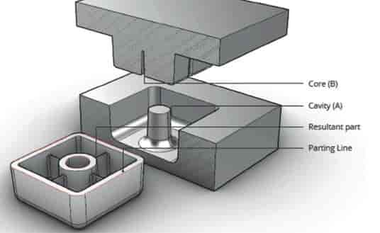
Part Fundamentals A part is created by two or more tools moving together to create a closed volume, into which plastic is injected under pressure.
In a 2 part tool the cavity (A) creates the quality outer surfaces and the core (B) creates inner details.
There are often extra “cores” sliding into the cavity to allow more complex parts.
|
|
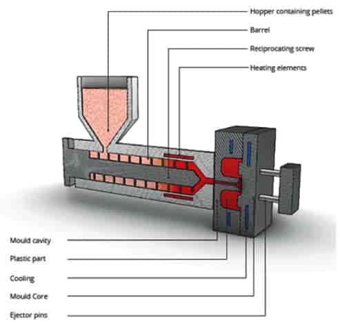
Injection Moulding Raw plastic is fed into the hopper as pellets. Within the hopper these are mixed with additives such as pigment, and fillers such as glass fibres to adjust the properties of the final part The material is then fed into the barrel, where a reciprocating screw rotates, moving the pellets towards the mould and compressing them.
The friction created in this process combined with heater units wrapped around the end of the barrel raises the temperature and the pellets are melted Once there is enough melted plastic in front of the screw, the ram moves forward squeezing material through a nozzle into the mould cavity where it cools and hardens.
|
 |
|
|
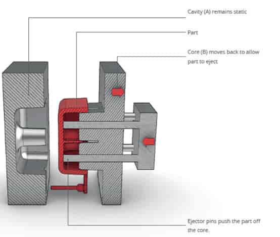
Ejection Throughout the injection process the tools are clamped tightly together. Once the plastic has cooled sufficiently to maintain its shape the tool opens, usually by the core and part moving backwards away from the cavity.
Ejector pins are then pushed through the core against the part, releasing it to drop free from the tool.
This process does result in a few witness marks on the part:
Parting lines: where the two halves of the mould meet. Ejector marks: where the pins meet the part. Normally these are hidden on the rear.
|
|
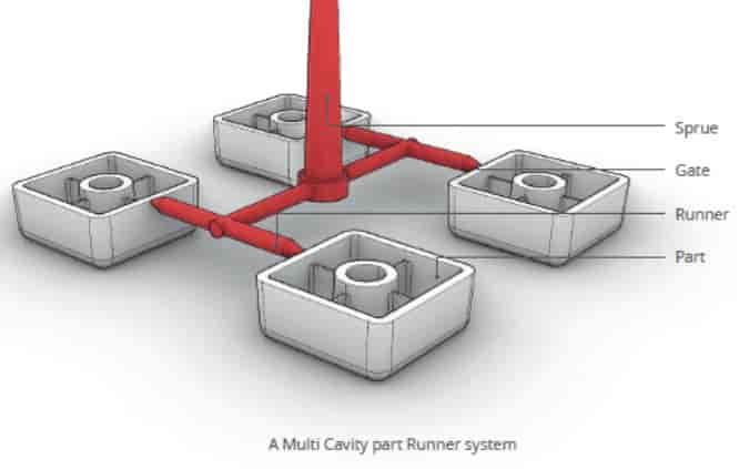
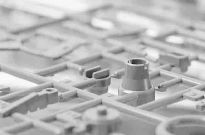
The Runner System Melted plastic enters the part through a network of channels in the tool called the ‘runner system’ There are usually 3 parts to this:
The sprue: The primary channel where material flows into the tool.
Runners: Smaller channels which guide the plastic to the gates.
Gates: The entry point to the part.
|
|
|
|
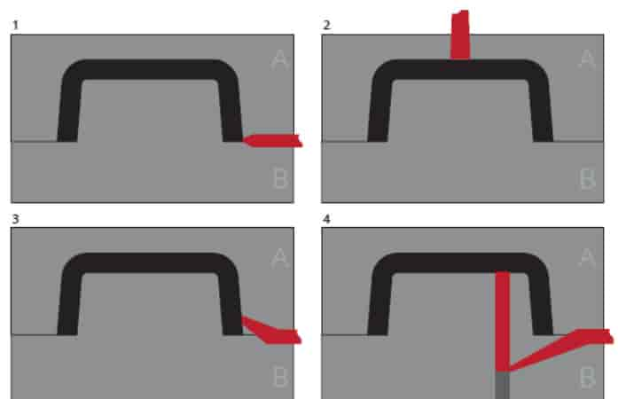
Gates Gates are the point where the melted plastic enters the cavity. The position and geometry of a gate control the flow into the part.
The diagrams to the right show some of the common approaches:
1. Edge gates are the most common, injecting at the part line where the two halves of the mould meet. The runner system is removed manually after ejection which leaves a small witness mark.
2. Direct gates connect from the spur to the top of the part to reduce material wastage on runner systems. This is ideal for very large parts but does leave a visible mark on the part.
3. Tunnel/Sub gates inject below the parting line. There is no need for manual removal of runners as they are snapped off on ejection. This is ideal for very large volumes.
4. Pin gates inject material from the inside of the part in the Core or “B tool”, away from the visual surfaces making them favoured for appearance. |
|
Before Tooling As with all mass manufacturing processes there are a few planning steps before committing to tool.
Is moulding the right process at this stage? High numbers of parts should be intended, and tooling cost factored in.
Optimising Ensure that everything that is needed from the design is specified in detail before starting tooling. Changes to steel tooling is costly and time consuming.
Specify Material, and Properties Every polymer has different flow rates and shrinkage, it always helps to know the planned material before tooling so the injection point can be designed appropriately.
Lead Times Time to part with injection moulding is long. Times are quoted to samples, and there are often other time constraints, such as finishing, shipping, production sampling, assuming the design is complete. |
 |